Vision-based Autonomous Driving: Vanishing Point and Perspective Transform
Vanishing Point & Perspective Transform
Vanishing Point & Perspective Transform
Autonomous driving through image processing
project propose : Compensate, via lane detection, for the error that arises when the driving direction is determined from the vanishing point
- Lines are detected in the image-processing stage, and the vanishing point where they meet is used to determine the driving direction (steering).
- The error that arises while the vanishing point is generated is handled by defining a box and checking whether the vanishing point has left the box.
- The 2D view captured by the camera is passed through a perspective transform to detect the lanes.
- A new interpretation is introduced by combining the vanishing point detected through the camera with lane detection.
Vanishing Point
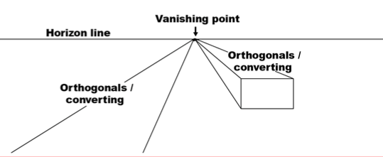
Lines that are parallel in 3D space do not appear parallel in a 2D image because of the FOV (Field of View). As a simple example, lane lines on a road are parallel in a bird’s-eye view, but are not parallel from the driver’s (camera’s) point of view.
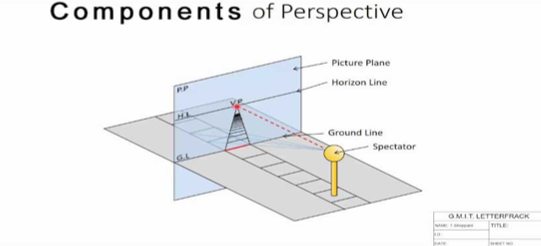
basic of concept
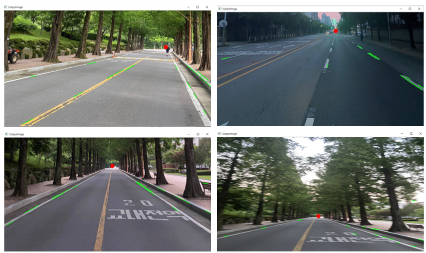
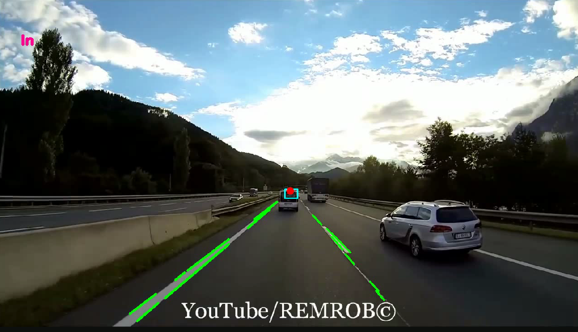
Vanishing point applied to a real image: the lanes are detected and their intersection is marked with a red dot.
Perspective Transform
A method that corrects an image captured non-parallel to the region of interest so that it appears parallel to the target. By setting 4 points and adjusting the proportions of that region, the image coordinates can be transformed.
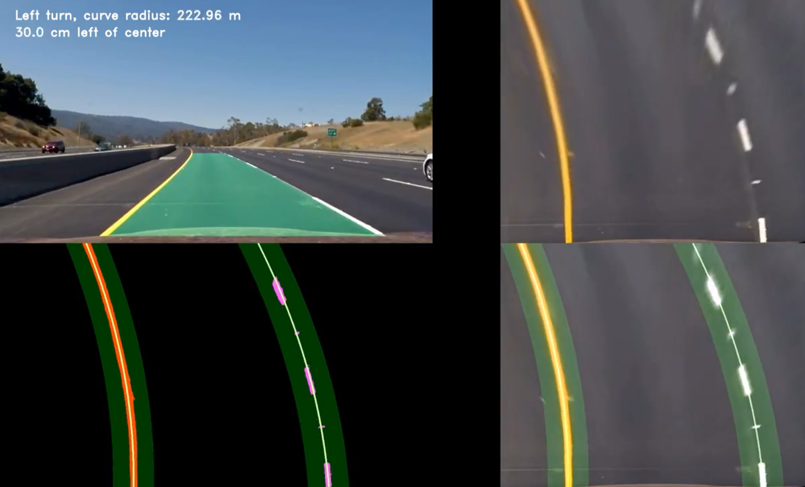 | 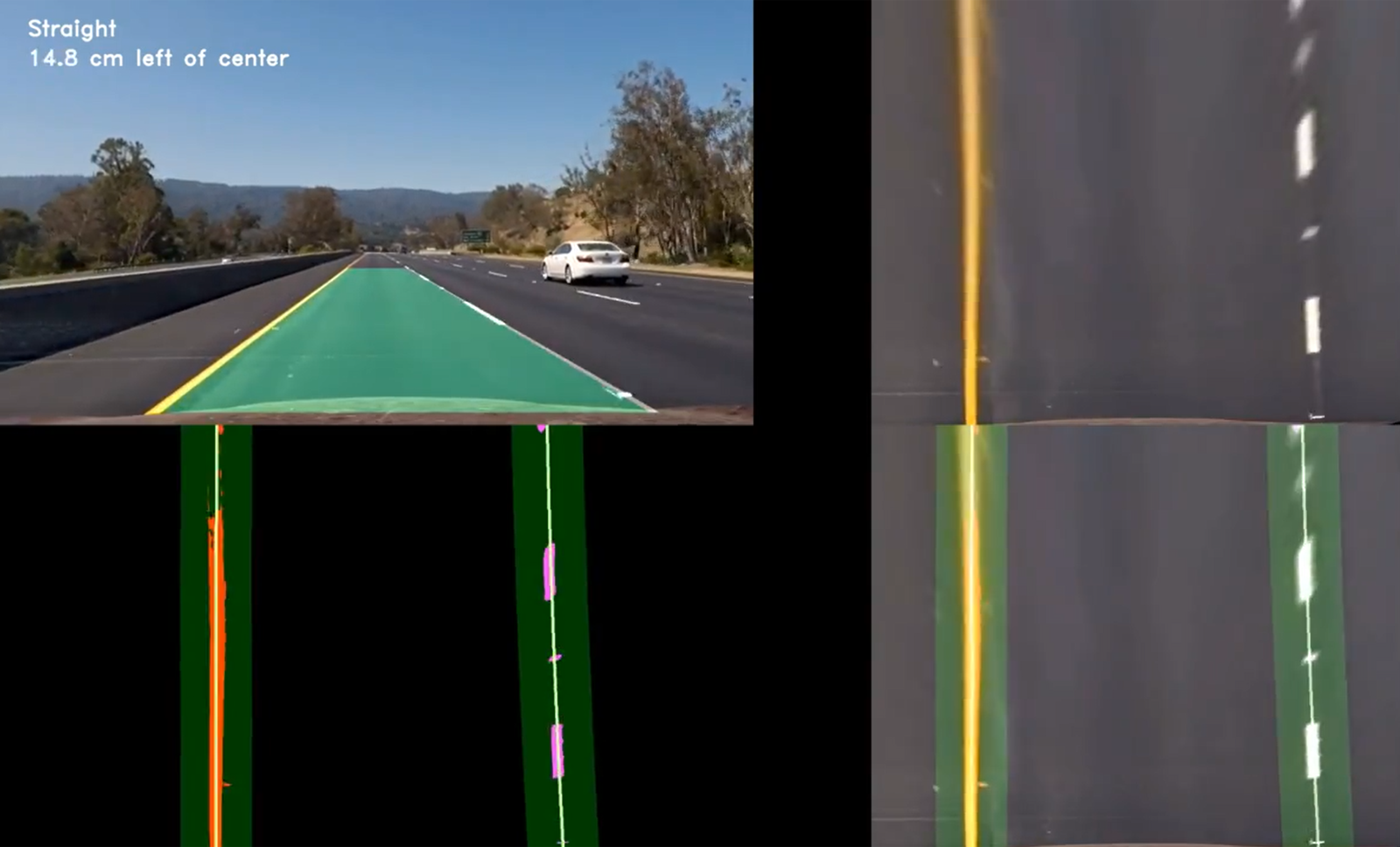 |
Applying the perspective transform to an arbitrary image changes the field of view as shown below, converting the region of interest (ROI) to the lane.
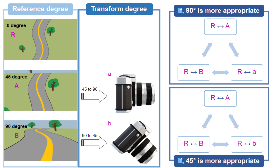
At the start of the project, tests were run with a camera field of view of 45 degrees / 90 degrees to determine which setting is more effective.
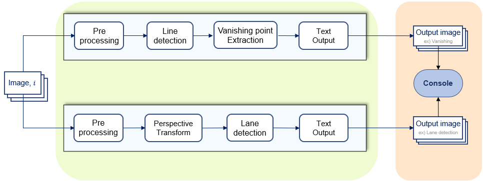
algorithm of project (flow chart)
Results
Vanshing Point
The range of the vanishing point within the image is defined by adjusting the box size
-
Applied the Gaussian distribution formula
-
To validate the bounding box, the coordinates of the region containing the red dot were checked and a Gaussian distribution was fitted
Vanishing point detection through Hough Transform Line Detection
(Additional explanation of Hough Transform Line Detection)
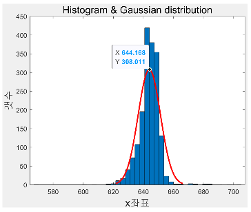 | 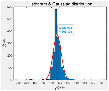 |
result of Gauissian Distribution for red dot.
Perspective Transform
The 4 pre-transform coordinates were selected on a straight section
- Can determine when the vehicle is not in the center of the lane. When out of range, the current driving state is visualized as text output
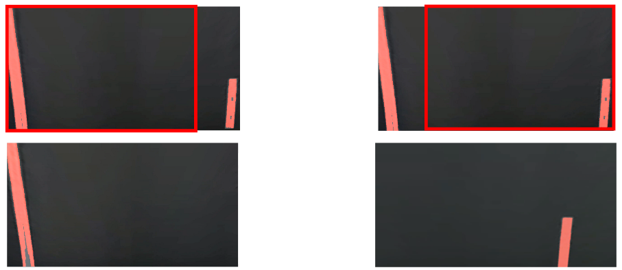
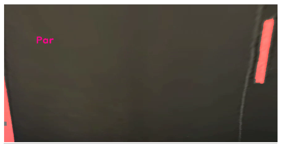
When both lines are detected, they are judged to be parallel.
Combining Vanishing Point & Perspective Transform
Complementary decision metric from the two techniques
-
Idea inspired by the confusion matrix
-
Decision metric for erroneous driving
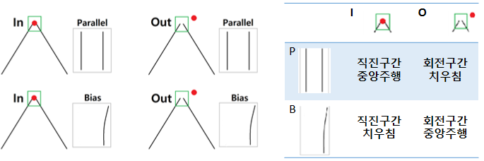
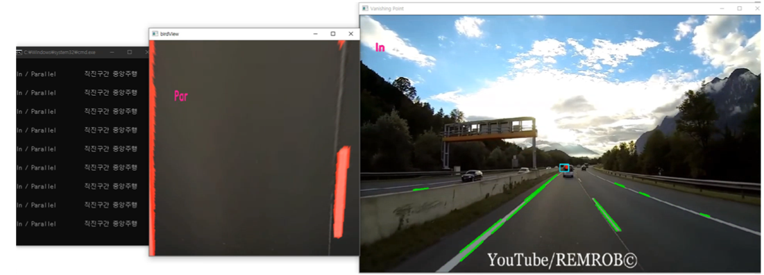
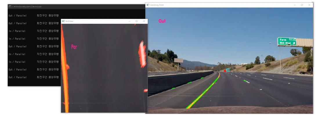
- The image outputs [In/Out] and [Parallel/Bias] respectively
- The console combines the above into [straight section, centered / straight section, biased, turning section, centered / turning section, biased]
Conclusion
- The bounding box determines whether the vanishing point indicates a straight or turning section.
- Lane detection with perspective transform determines whether the vehicle is biased to one side.
- A technique is proposed that improves driving stability through the complementary combination of the two.
- The proposed method was validated using an open driving video dataset.
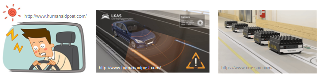
Applicability
Reference Papers
vanishing paper.pd.pdf (original PDF not attached)
TIP2012.pdf (original PDF not attached)
Vanishing_Point_Detection_WACV2017.pdf (original PDF not attached)